![]()
![]()
![]()
![]()
![]()
![]()
![]()
![]()
![]()
![]()
![]()
![]()
![]()
![]()
![]()
![]()
Web Updated;
06/07/2011
![]()

Mail me!
Sign the guest book
Construction and General Theory
| The concept of a "cage dipole" has long been
established.
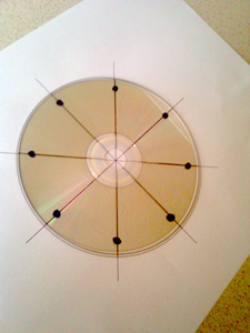
The earliest cage dipole designs I could find were referenced in the late 1960's and also in the ARRL antenna Book (21st Ed) which is a superb reference. The problem I had with the standard design was my available space for a full sized 1/2 wave Dipole at 40m. I had investigated lumped loading and linear loading but knew that some form of device must be added to reduce the overall length of the antenna to enable installation within my loft space which was a mere 6m end to end. I had not seen a half wave dipole which incorporated both bandwidth widening using a cage and loaded within the same antenna. I modelled the idea in MMana-Gal which is produced by Makoto Mori (JE3HHT) Alex Scheweiew (DL1PBD) and Igor Gontcharenko (DL2KQ) with initial results looking promising. I decided to build the antenna just to see if the idea would work, the cage design hopefully offsetting the narrow bandwidth produced by coil loading. First the cage needed supporting and I used some old CD's hanging around the house and formed a template to enable 8 equal segments for the 8 wires which would form the cage.
|
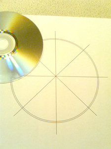 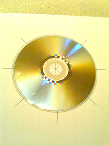 |
| Once I had made a paper template with a diameter of 122mm (cd
being 121mm Dia) and extension construction lines to enable easy lining of
the cd with a permanent CD marker pen.
Then I hand drew on 8 location marks for the drilling which would be where the wires pass through. Plastic CD's / DVD's are quite brittle when drilled so a pair of safety goggles are necessary to protect your eyes. I found that placing the cd's on a block of MDF reduced the risk of the last CD in the pile from shattering as the drill broke through. Drill bit was a 1.6mm HSS and I found with gentle pressure I could drill 4 to 5 CD's at once. This process also helped getting the hole positions equal. |
  |
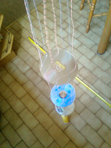  |
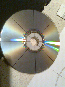
I had 12 CD's in total (2 broke whilst drilling) to spaced
the 6 equally between each leg. This worked out approx 400mm centres with
the end being slightly less.
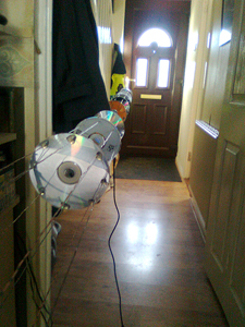
String the wires (all cut for 2.1m) through and glue in place with hot plastic glue gun. Tip! only use a small blob of glue otherwise it takes too long to set and movement can sag the individual wires forming the cage. Lay out the two legs and use the first one as a template to ensure the second one mirrors the first. The loading coils are made of 43mm outside Diameter PVC pipe available in B&Q (UK hardware store) Complete details can be found on the Diagram, but the pipe (former) length is 150mm with 2.5mm² insulated wire, close wound with 36.5 turns making a coil length of 127mm. Loading coils are connected with bolts to the ends of the cage legs (opposite end from the coax feed point) Finally a 2.5mm² insulated wire is soldered onto the unconnected end of the coil and cut for 2m. (adjustments in this length subject to VSWR and installation environment. |