![]()
![]()
![]()
![]()
![]()
![]()
![]()
![]()
![]()
![]()
![]()
![]()
![]()
![]()
![]()
![]()
Web Updated;
02/04/2012
![]()

Mail me!
Sign the guest book
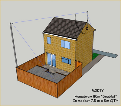
The Home QTH 80m "Doublet"
I have now developed what I truly believe is the most efficient widest band antenna I can operate from this present QTH.
The doublet for those who are not conversant is basically a dipole tuned for the lowest frequency required, fed in the middle with a low loss ladder line (normally) direct to a balanced Aerial Matching Unit. Unfortunately my Comet CAT 300 will not accept a balanced ladder line output so a different approach was required.
Click on the photos for a larger view!
Design Criteria:-
1. To operate on the following bands:- 80m, 40m, 30m, 20m, 17m, 15m, 12m, 10m and 6m.
2. To be as efficient as possible thus having the lowest losses.
3. To be able to handle the legal UK power limit of 400w (operating at up to 100w at present but needed future proofing!)
4. To cause no interference to neighbours or the household.
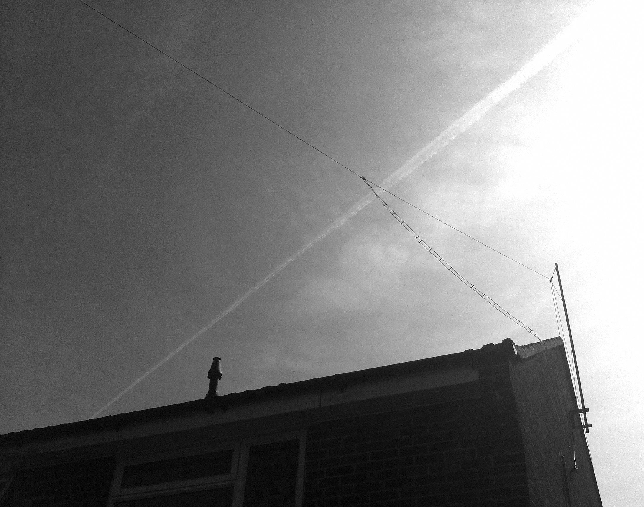
Approx. level height above ground is 12m. I have taken the photographs in black and white because the wire insulation colour of blue means against the sky it didn't show on the colour photos! (A bonus for being neighbour friendly) The poles are also painted with matt grey primer.
The installation is as follows:-
One end of the wire starts at 6 foot fence level and travels
at approx 60 degrees to the top of the main support pole. (This is situated
between the fir trees to also minimise impact to neighbours) Photo above right.
It then travels towards the gable end support pole (Photo above left) where the feed point
is and the vertical homebrew ladder line.
I sprayed the ladder line and white coat hanger spacers matt black to provide a
better match to the house.
From here the other end of the wire follows the line of the pitched roof to the first floor window height, where it travels vertically downwards to approx 30cm above floor level and then doubles back approx 1m. All connections to the house are made by heavy duty electric fence insulators fixed into the brickwork with raw plugs.
Going back to the centre and the feed line, (Photo above left)
the feed line travels across the roof edge to the gable end, where it connects
to the 1:1 Balun. The Balun connects to a short (500mm) piece of RG8X Mini Low
Loss Coax where it travels through the wall into the loft space.
From within the loft space a homemade MDF plinth houses the LDG Z11 Pro ATU and
a Maplin 12V 7AH Gel battery. From the ATU RG8X Mini travels the 9m into the
second floor radio room.
This of course means that the impedance miss match from the
antenna to the radio is matched to 50 Ohms before the signal travels through the
coax. This reduces loss significantly and improves reception and transmission.
On 100 watts from the radio I am showing 95 Watts to the antenna.
The Z11Pro does get twitchy at times on 80m, where modulation peaks on LSB cause
the unit to hunt again once tuned.
I have earthed the Z11 Pro and ensured that the casing forms a good earth to the
rest of the unit, but it still has a mind of its own.
I have also bypassed the Z11pro and matched the aerial from the CAT300 next to the rig and the losses are insignificant.
This aerial works really great, I have done exhaustive tests and no RFI is being radiated within the house, and no comments from the neighbours.
This just proves that you can work 80m's from a very modest QTH! Below is a quick Google Sketchup diagram which makes it easier to understand.
Have fun, if you would like any further information please email me.